We at Crack4sure are committed to giving students who are preparing for the Autodesk RVT_ELEC_01101 Exam the most current and reliable questions . To help people study, we've made some of our Autodesk Certified Professional in Revit for Electrical Design exam materials available for free to everyone. You can take the Free RVT_ELEC_01101 Practice Test as many times as you want. The answers to the practice questions are given, and each answer is explained.
Refer to exhibit.
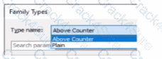
A family in a project contains the following types:
The following edits are made in the Family Editor and loaded into the project:
1. The type Plain is renamed to Standard
2 A new type is added named GFCI
Which types does this family now have in the project?
1. The type Plain is renamed to Standard
An electrical designer is routing conduit through a building model to coordinate with other disciplines, the electrical designer wants to view selected components in a cropped 3D view.
With the conduit components selected, which tool should the designer use?
How can an electrical designer see changes from other users without saving their own work to the central model?
Refer to exhibit.
(The image is presented in Imperial units: 1 In = 25 mm (Metric units rounded).)
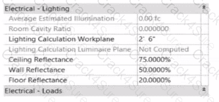
In the space properties for the space, the Lighting Calculation Luminaire Plane is Not Computed. What is causing this issue?
Refer to exhibit.
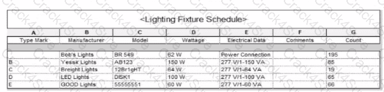
Which two actions were used to create this light fixture schedule? (Select two.)
A project has 24 branch panel schedules that all need the same formatting changes. What should the electrical designer do?
Refer to exhibit.
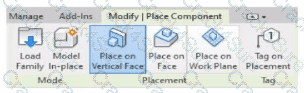
An electrical designer is placing electrical equipment. When the electrical designer selects a component in the contextual ribbon, the Placement panel appears in the contextual ribbon.
Which condition does this Placement panel indicate?
Refer to exhibit.
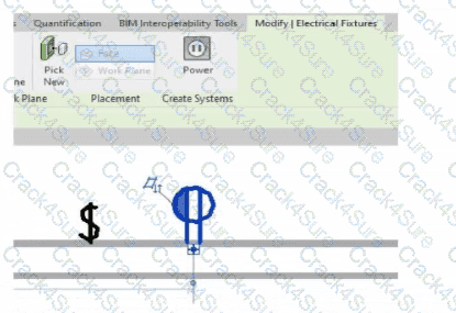
An electrical designer is circuiting a dwelling unit. The receptacle (electrical fixture) shown must be controlled by the switch (lighting device) shown to switch a plug-in lamp When the receptacle is selected, Revit does not provide an option to add the receptacle to a switch system.
What is causing this issue?
An electrical designer Is working on a workshared model.
Which two worksharing display settings can the designer use to visualize model elements that have no ownership? (Select two.)
Which Revit command is used to map a Keynote Table file?
Refer to exhibits.
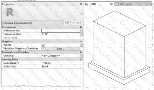
When loaded into a project, the family displays as below in plan view.

The electrical designer is satisfied with the line color and weight of the transformer because it matches all other electrical equipment in the project. However, the designer wants the housekeeping pad to display with different line properties as shown below.

How can this be achieved?
An electrical designer creates a simple family of a transformer with a concrete housekeeping pad using two rectangular extrusions. Both extrusions and their properties within the family editor are shown.
An electrical designer wants to add a parameter to a lighting fixture schedule without editing the families. Which parameter type should the designer use?
Refer to exhibit.
(The Image is presented in Imperial units: 1 In = 25 mm [Metric units rounded).)

What is the electrical designer trying to do as shown in the exhibit?
3 Months Free Update
3 Months Free Update
3 Months Free Update

TESTED 09 Jul 2026